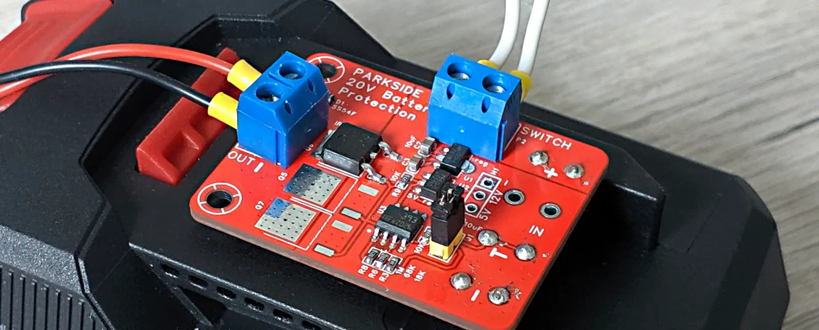
PARKSIDE battery breakout/protection board
| Latest PCB version is 1.2, read important updates at the bottom! |
A year or so ago I bought a PARKSIDE jigsaw with 20V battery, with the intention to also use the battery in DIY projects. PARKSIDE is a brand of tools from LIDL chain store with decent quality for non-regular work and competitive prices. Turns out, this particular tool ecosystem does not include power control inside the batteries, cell terminals are simply routed to outside without any MOSFETs in between. This seems to be the usual case where the lithium product range evolves from NiMH era, where there protection was in the power tool. Interestingly, cheap noname batteries usually have protection built-in, though the reliability of those is questionable. So to use the PARKSIDE battery in DIY projects, external protection is preferable.
I believe there are cheap 6s protection boards on aliexpress, but all I could find were modules with per-cell balancing connections, intended to be installed into the battery itself. Also, one feature of this battery pack is that it has a pin that not only provides temperature reading, but also undervoltage alert. And I didn’t want to duplicate this logic inside and outside the battery. So with these considerations in mind, I ended up designing my own protection PCB.
Requirements
-
Disconnects load from the battery,
-
Conducts some serious current (this is intentionally vague, as I will use it in low-power situations, so this requirement is mostly for self-education)
-
Uses fault information provided by battery pack.
-
Temperature reading not necessary (presumably overheating will be reported by battery itself)
-
Keep it simple, no MCU, firmwares and stuff.
Principle
T pin in the battery is connected to ground via a 10k thermistor and a transistor.
In the event of under-voltage or over-current (I don’t actually know if battery handles over-current situation, but there seems to be a shunt/fuse inside) the transistor goes off, and the pin becomes floating. Under normal conditions the transistor is on and the pin has around 10k pulldown to ground.

External circuitry (at least on the PARKSIDE soldering iron) is providing 5V to that pin via 10k pullup and measures the voltage. If it’s around 2.5V, all is ok, otherwise there is a fault.
There is one quirk though, in a form of some kind of a power saving feature in the MCU of the battery. if it does not sense voltage on the pin, it will turn the MOSFET off. My first schematic was providing around 2 volts to the pin, and the battery shut the pin off after couple seconds.
This video from bigclive has schematics of a Parkside soldering iron that plugs onto such battery, so it helped a lot while designing the project.
The design


Project electronics page: https://oshwlab.com/positron96/powertool-battery-protection
There is 2 stage power supply on the PCB, 12V and 5V, both via LDOs selected to have a low quiescent current (ht75xx). 5V is fed to the pin through 10k resistor. The voltage is fed to a negative input of a comparator (l393), positive input of the comparator is supplied with reference of around 4V from a voltage divider. Since the comparator cannot handle rail-to-rail inputs, it needs to be powered with higher voltage, and this is where 12V comes into to play. So the output of the comparator is 0V if there is a fault, and pulled to 12V in normal conditions. The output is fed to gate of the low-side power MOSFET.
Using 12V here also allows to use a non-logic level MOSFETs, but I bought a IRLML (a logic level MOSFET) for the first iteration of the board, so I used these. While researching I found DP4080 MOSFET in my XY-SK120X PSU. It’s available at LCSC at decent price.
First version of the design had single power [1], no comparator, and directly fed T pin voltage to an inverter BJT, and then to a gate of the mosfet. This didn’t account for power saving of the battery, so the battery shut off the output after couple seconds.
Current handling considerations
To handle high currents, the PCB has space for 4 parallel MOSFETs, uses copper pours for high-current paths and there are bare copper areas to add solder traces if needed.

I don’t have proper devices to overload the battery, cannot measure the temperature of the PCB, so I can only hope that the PCB can handle some 10 amps. Hightest power test I did was to power a Pinecil with it, at peak it consumed 45W (so around 3A), the MOSFET remained cold to touch.
I have no experience designing high-current PCBs, this is my first one, so any suggestions are much appreciated. In any way, does not seem like I will use it for high current projects.
2025.09 Update
I’ve checked how the circuit works in overdischarge conditions, and it works! Battery indicates overdischarge fault at around 13V (2.6V per cell), which shuts down the protection module.
2025.10.13 Update
After trying to use the PCB to charge a laptop (using USB-PD DC-DC concerter), I found out that the battery performs some weird tricks on T pin. Turns out, during normal operation MCU inside the battery disconnecs T pin for a fraction of a second regularly, couple times a second. Floating T pin is treated by my board as a "battery says it’s dead" (which is true for undervoltage situation), which causes power MOSFET to turn off.
I didn’t notice it before as I didn’t put a lot of load to the board, and there was a USB-PD capacitor at he output, which smoothed drops of voltage. With 65W laptop charger the capacitor is gets emptied quickly, so I noticed that power disconnects regularly.
Why battery does that I don’t know, but this happens with both batteries I have.
To account for these disconnects of T pin, I added a low-pass RC filter at the input of the comparator. Now MOSFET shuts down only when T pin is disconnected for longer periods, should be around 1s.

PCB is now at version 2.1.