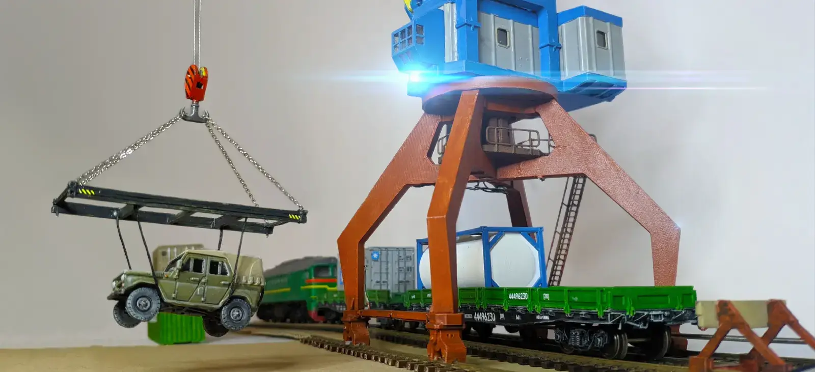
Level-luffing crane, motorized and 3D printed
The project is about creating a 1/87 scale model of harbour level-luffing portal crane (also called horse-head crane) with 4 degrees of movement. The motorized functions are:
-
rolling the whole crane on the rails,
-
rotating the crane,
-
tilting the boom,
-
raising and lowering hook.
In addition, lights on the crane are also controllable.
Originally I also wanted the "hook" to be an electromagnet or grabber, but since then I’ve settled on an ordinary hook, which means that attaching loads is manual.
The project consists of creating the mechanical structure that can do the job, and electronics and firmware to control it.
There are similar off-the-shelf products, e.g. ROCO 40110, 41290, 41296 (and some other SKUs). Those look like they are from different era, around WW1 to WW2 maybe, and from different region.
There is a russian variant of this article.
Mechanical features


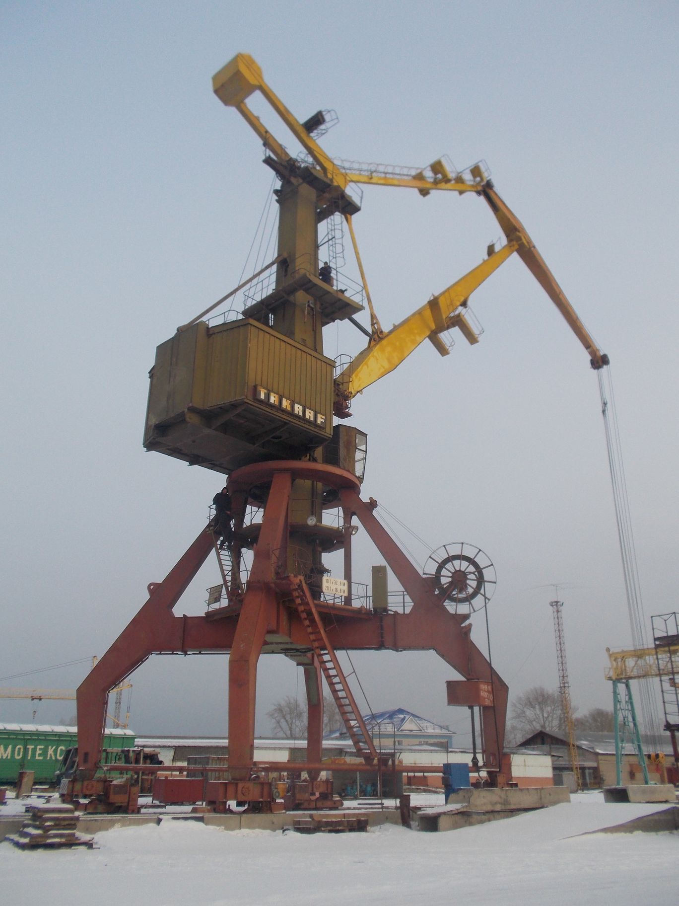
The crane is designed after 2 Eastern European/Soviet portal cranes, Kirovets and Albatros. Most of geometry is taken from Kirovets crane, except tieback, which is made of cables on the real structure, but is plastic on the model. The portal and rotating hub are taken from Albatros as it allows larger rotating hub inside.


The model is not to scale. Judging by leg span (10500mm to 90mm) and height, scale of the model is around 1/116, ~25% smaller than 1/87. In particular, the portal can fit only 1 railroad track, conforming to NEM-102 clearance. (it accommodates 2 in real life).
The model was designed in Fusion 360 and then is 3D-printed. It uses a combination of FDM 3D printing for large load-bearing parts and resin 3D printing for small decorative parts or precision mechanical parts like (small) pulleys.
Moving joints are assembled with pins (made from paperclips), non-movable components are glued or screwed together with small self-tapping screws in places where later access might be needed (for inner components and electronics).
An in-progress video of superstructure rotation and boom elevation. Uses quick-and-dirty firmware for Arduino and Wii Nunchuck:


Slip ring

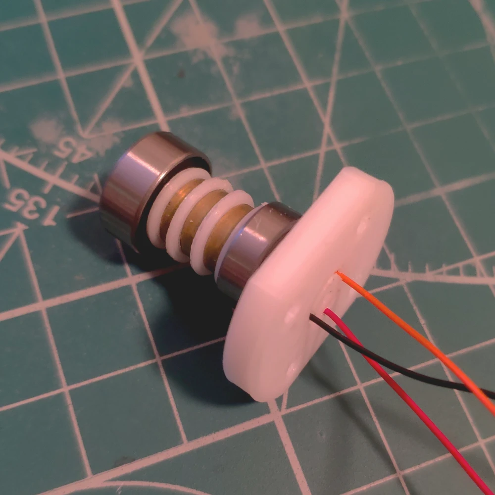
The 3-pole slip ring in the base of crane tower needs to hold the superstructure and to pass electrical signals and power. It is expected be able to carry tilting forces caused by boom extension and load movement. This current design has 2 ball-bearings with 6mm and 8mm bore diameter and is printed with FDM.
To make contacts, a brass pipe was cut to produce rings, and wipers are made of phosphor bronze wire (0.4mm).
All in all, this works, but not particularly satisfying (there is some axial shift, questionable contacts durability), so next time I’d rather design a new one or just use a commercial slip ring in the future projects.
Linear actuator
Linear actuator is used to move main crane jib. It consists of a 6mm gear motor and 2mm threaded rod, a bearing to hold it centered, a bronze threaded nut to slide along the rod and resin printed parts. You can see it in action in the video above.
At first I tried to not over-engineer it and use an ordinary RC servo, but even a 9g servo was too large to fit. Smaller ones are definitely not strong enough.
The actuator doesn’t have any end stops, so must be operated by trained personnel! Otherwise the threaded rod just snaps off from the nut and the boom falls down.


Winch
A winch is an integral part of a portal crane. The winch model was designed for this project and is described in this post.
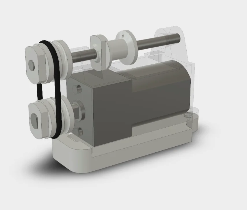
It uses an N20 gearmotor and 2 nitrile rubber (FKM) O-rings to make the construction smaller and place the drums above the motor. The O-rings also conveniently serve as a torque limiter as they will slip under heavy load.
Here is it in action:
On crane cables
Turns out, it’s very difficult to find material for a good scale model of a hoisting cable. There are some conflicting requirements for the cables, such as:
-
It needs to be thick enough for realism sake
-
and dark colored, also for realism,
-
It must be flexible enough to go straight down with minimal weight,
-
It must not be braided as those twist after some time of inactivity.
So far I’ve tried ordinary sewing thread that I had lying around (too thin and braided), waxed leather-grade thread (thick, good flexibility but braided), polyester thread of specific thickness (tangles but otherwise perfect), black fishing line, number 1.0, i.e. 0.16mm (not braided, but too thin and not flexible enough), "elastic fishing line" (white and thin, not braided, way to stretchy), braided thick thread (too thick and tangles).
I ended up using a "multifilament braided fishing line 0.12mm" (from aliexpress). It is really strong (and hard to cut actually, not every clipper cuts it), a bit too rigid and not flexible enough to unwind under the weight of the hook.
Having obtained the knowledge of all other options, I think a braided sewing thread could work better then multifilament one, but it needs to be twisted properly so that it doesn’t tangle on its own. (more specifically, it must not be twisted when installing). This means that "not braided" requirement above is probably not as strict and is there due to lack of experience. This is to be tested on a next project involving threads.


Hook
The winch performance depends on weight at the end. If the line is not tensioned enough, it will not unwind properly, get tangled and will not move down. This is not a problem when there is some load attached to the hook, but without load, the hook itself needs to be as heavy as possible. To achieve this, I tried to make the hook pulley housing by casting solder.


The end process is described in detail in this post. Earlier attempts are described here.
The hook itself is resin-printed and glued to the pulley housing with the help of pin (made from paperclip).
Electronics

Here is a scheme of electronics and connections. 2 custom PCBs were used in the project, one is placed in the crane tower room, another on the ground, ideally below the diorama. PCBs were developed in EasyEDA and manufactured by JLCPCB.
Motor board and connections
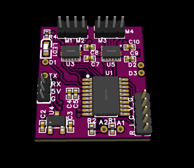
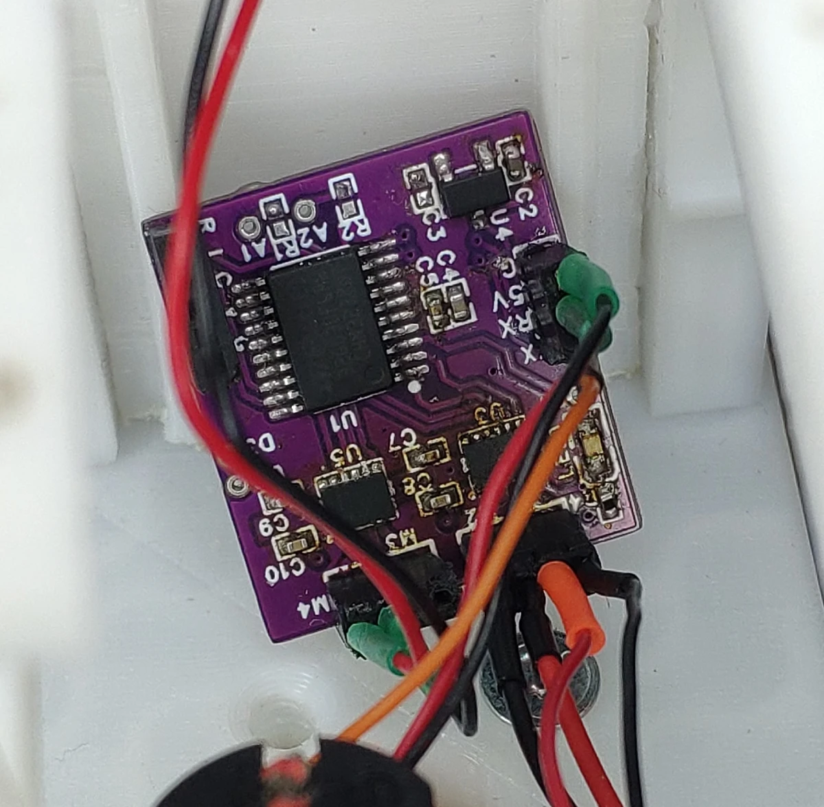
Electronics needed to control the crane is rather straightforward - an MCU, one H-bridge per motor and some LEDs. However, I realized that an Arduino and motor modules will not fit into the housing of the crane, so I designed my own PCB with a STM32G0 MCU and 2 DRV8835 dual H-bridges. The board can control up to 4 motors, but only 3 are used as 4th motor is on the ground and is controlled from a ground board. The motor functions controlled by this board are tower rotation, boom tilt and winch.
The motor board has a separate project page.
One projector lamp is fixed near the cabin. It is a 0603 warm white LED that is also controlled by this board.
In retrospect, it would be nice to add a more LEDs to the project to make it look lively.
Electric connection between ground and movable crane is made over rails that provide GND and +5V, and data is communicated over steel threaded rod that moves the crane along the tracks. The rod moves a brass nut attached to the portal, on the ground the rod passes through a brass eyelet, wires are soldered to the nut and to the eyelet. For power, the wires are soldered to the rails on the ground (these are just ROCO tracks cut into separate halves), and crane slides on phosphor bronze wires. There are no wheels on the crane.
From the portal 3 wires go through the slip ring into the crane control room where the motor board is located.
As it turned out, connection over the threaded rod is the most problematic as the connection frequently interrupts when the crane moves, and sometimes the crane needs a push to restore the contact.
To mitigate this to an extent, the MCU firmware checks that the data is arriving constantly and, in case of timeout, stops all motors. This way the crane does not crash in the event of connection loss. On the ground module, firmware is responsible for sending updates at regular intervals.
Communication happens over 1-way UART link with human-readable ASCII commands to move motors and control LEDs.
Ground control board and human interface
The ground control station consists of an Arduino Nano, DRV8833 module (a dual H-bridge), and a Wii Nunchuck (or clone). This is mounted on a simple custom PCB that mostly consists of pin headers. The PCB has a separate project page and is used in other projects as well.
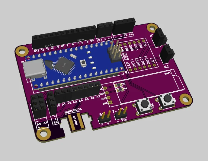

The motor that moves the whole crane along the track is an N20 gear motor of 3000RPM/12V, which is undervolted to 5V and geared down by threaded rod transmission. It is controlled via H-bridge on the board.
When the crane is installed on a layout, the motor and its transmission should be hidden below ground level somehow. But since there is no layout at the moment, the motor remains mounted near the crane for everyone to watch.
Instead of fixed-mounted joystick (like the one ROCO makes for their crane), a handheld Nintendo Wii Nunchuck (or a cheap clone) is used. It has a 2-axis joystick and 2 buttons, this seems enough to control 3 DoF crane, a winch and lights. It also has accelerometer, which might be useful to control more functions.
The controller can be easily connected to Arduino with I2C interface with the use of readily-available Arduino libraries.
The whole project is powered by 5V phone charger or a powerbank.
