My first flex PCB
Last time I noticed that JLCPCB economy offer expands to flex PCBs, and, naturally, wanted to try one.
The goal of this PCB is to place LEDs on rear side of the truck. This is usually done by just gluing separate LEDs to the model (and soldering wires to LEDs beforehand). With this PCB it should be easier to solder the LEDs to PCB first (using hotplate or heat gun, for example), and then glue one PCB to the model.
Normal FR4 PCB would be too thick for this application because of its thickness (~1mm) and manufacturing limitations (e.g. min 0.3mm distance from copper to PCB edges). With flex PCB thickness is not a problem at all (it’s ~0.1mm), and it should be possible to just trim the edges to size manually.
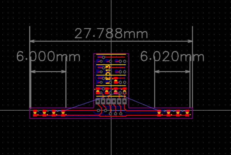
The PCB holds 8 0402 LEDs, 4 on each side of the vehicle. This corresponds to marker light, turn signal, reverse signal, brake signal. The PCB drawing also has some copies of 4 LED portion (to be cut off and used separately).
The PCB seems to turn out quite well. I could easily cut the PCB into pieces with scissors.
Here is me flashing the LEDs manually with diode-testing mode of the multimeter.