Starting a new project: RC offroad truck in 1/87 scale
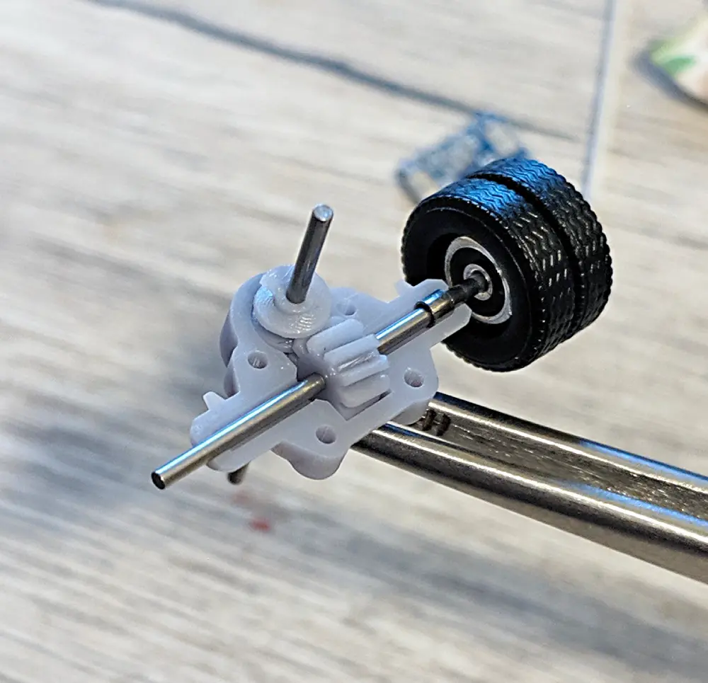
So I finally started a new RC truck project, this time an offroad 3 axle truck, with suspension and at least 2 rear axles driven.
I chose basic principles to be the same as in this project. It uses ready made brass components, which I intend to replace with 3D-printable ones. Its drivetrain has "pendular suspension" [1] on both live axles and steerable+driven front axle.
Transmission
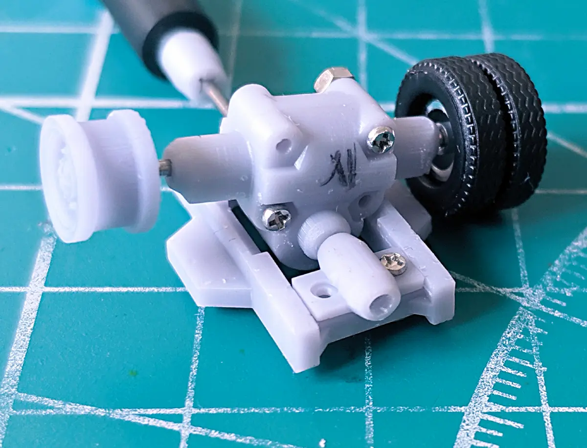
And this starts with a new axle gear hub. First, since it’s offroad this time, the wheels are larger and there is more ground clearance, which means there is more vertical space for the axle gear hub. Second, 2 rear axles mean that driveshaft must go through first axle hub, which means that my previous bevel gear design will not be ideal. It could work if I split the driveshaft into pieces, but then it’ll be difficult for it to suspend the vehicle.
Usually makers use metal worm drive here, for example, look at this nice building video.
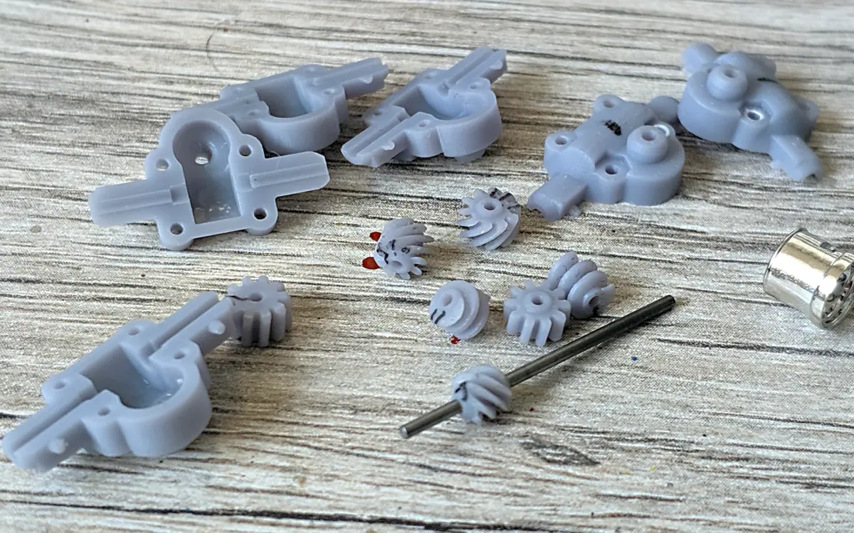
To experiment, I tried doing the same and 3d printed a worm drive in resin. First attempt printed fine, and shows the problem of insane amount of friction. The gears fit too well and basically bind together.
Second version with more clearance ran very well, so this approach seems to be viable.
Otherwise another thing to try is a ceramic-filled resin, Siraya Tech Mecha White. I still intend to do this, as I have an opened bottle.
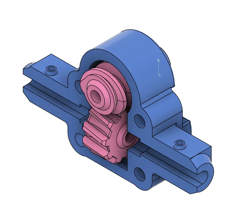
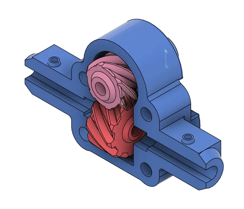
Another approach is to use a whole different gear geometry. The project needs something where axles are offset from one another, like in a worm gear. Here 3D printing has an advantage over metal as we can print very complex shapes. For example, a very cool-looking hypoid gear that is often used in real cars. It allows for offset axles and in terms of friction is somewhere between bevel gear (no sliding motion at gear contact point) and worm gear (a lot of sliding motion). It also allows more compact design, as axles can have less offset then in worm drive.
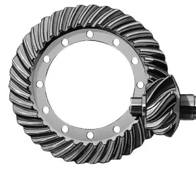
Thing is, hypoid gears have very complicated math behind them and are freakishly complicated to design. In fact, there is no video on YouTube that shows how to do that in Fusion 360 from scratch (or any CAD for that matter), while there almost any other gear type is available.
Easier gear types can be generated by Fusion 360 plugins, "GF Gear Generator" in particular, but hypoid gears are out of the question. So far I’ve found 2 options to generate the gear set:
-
MITCalc is an MS Excel document that generates profiles that you import into CAD (it’s paid, 30 days trial. I use libreoffice and don’t have any of the supported CADs, so I didn’t try it)
-
Site that gives you numbers and formulas to input into Blender. Unfortunately, it refused to produce gears for my dimensions, which suggests that I have too extreme values (too big axis offset for too small size).
So I switched to a simpler gear set, crossed helical gears. They are very similar to a worm drive, but reduction is much smaller and amount of friction can be somewhat controlled by changing the angle of the contact line.