The right way to read LocoNet on 3.3V systems
As part of updating my DCC Command station, one of the most critical circuits to refresh was the LocoNet receiver interface.
Turns out, my last circuit wasn’t 100% stanard-compliant, and I haven’t found anything better, so here is an article about proper LocoNet receiver schematic that works for 3.3V systems.
Analyzing the previous iteration
Most existing DIY LocoNet designs (like FREMO FRED, MRWAA design or anything else that can be found in Google) were designed around 5V systems using microcontrollers like the ATmega328. In those older 5V circuits, you typically see simple voltage dividers that scale the 12V–15V LocoNet line down to a 5V logic window, or using a comparator.
There aren’t much designs that use 3.3V MCUs like the ESP32. When making the first version of the Command station, I designed the circuit with an LM393MX comparator with 1V reference voltage, sclaing down LocoNet signal to 1V and comparing it.
It worked fine on my 12V layout without problems, but, when refreshing the circuit in 2026, after analyzing the specification one more time, I stumbled across the requirement that maximum LocoNet voltage can be 24V and decided to do it right this time, respecting high voltage tolerance requirement.
Here are actual requirements from "LocoNet Personal Use Edition 1.0 SPECIFICATION" document:
-
Logic "1": voltage above +4.0 Volts with respect to ground conductors.
-
Logic "0": voltage below +4.0 Volts with respect to ground.
-
1.0 volt of hysteresis centered on +4.0 volts.
-
Maximum voltage is +24V and nominal is +12V.
-
Minimum receiver input impedance is 47 Kilohms, measured between bus and ground pins.
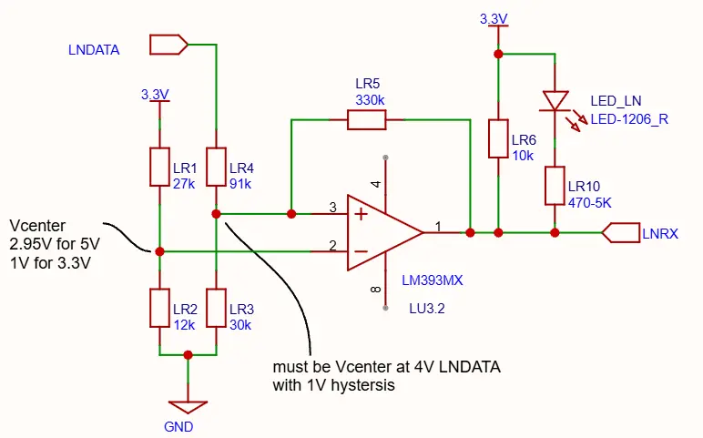
The math behind the previous setup
-
The Threshold Reference: The reference voltage divider used LR1 (27 kΩ) and LR2 (12 kΩ). Powered from 3.3V, this created a steady reference point at Pin 2 (Vcenter) of 1.015V.
-
The LocoNet input scaling: The input network used LR4 (91 kΩ) and LR3 (30 kΩ). When the LocoNet bus hit its standard transition threshold of 4.0V, the voltage at Pin 3 became:
\[4.0 V \times \frac{30 k\Omega}{91 k\Omega + 30 k\Omega} = 0.992 V\]This matches the ~1V reference idea, cleanly tripping the comparator right at the official 4.0V LocoNet mark.
The problem
When using an STMicroelectronics LM393, the chip has a strict Input Common-Mode Voltage ceiling (Vicm) of VCC - 1.5V. It means that at a 3.3V system voltage, the voltage at Pins 2 and 3 can never cross 1.8V.
If LocoNet is supplied with maximum voltage of 24V:
Not only does 5.95V completely exceeds the ST comparator’s 1.8V functional limit, but it risks feeding current back through the ESD protection diodes straight into the 3.3V rail, risking system-wide instability or fried silicon (admittedly, that current would be miniscule).
The upgraded, 24V-tolerant circuit
To fix this, the attenuation ratio of the input divider had to be made much more aggressive to compress a 24V spike under 1.8V, while keeping the switching point securely anchored at 4.0V.
Also, the new design values are chosen from E12 series resistors, eliminating the need to buy high-precision or rare components.
Hardware bill of materials
-
LR4 (Input Upper): Swap from 91 kΩ to 150 kΩ
-
LR3 (Input Lower): Swap from 30 kΩ to 10 kΩ
-
LR1 (Reference Upper): Swap from 27 kΩ to 120 kΩ
-
LR2 (Reference Lower): Swap from 12 kΩ to 10 kΩ
-
LR5 (Hysteresis): Upgrade from 330 kΩ to 500 KΩ
-
LR6 (Output Pull-up): Leave as is. Can be lowered from 10 kΩ to 4.7 kΩ for crisper high-speed data edges to the ESP32 RX pin
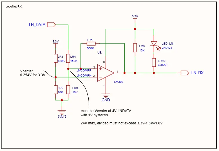
Verifying the new math
1. The 24V safety With a maximum 24V spike on the bus, our new 150k / 10k input divider clamps the maximum voltage seen by Pin 3 to:
1.50V gives a solid 300mV of safety margin right under the ST LM393’s 1.8V limit.
2. The 4.0V threshold With the new reference network (120 kΩ and 10 kΩ) running on our 3.3V rail, our target reference voltage at Pin 2 drops to:
If we reverse the input divider math to find out exactly what LocoNet bus voltage hits that 0.254V reference:
The circuit detects transition at 4.06V, perfectly protecting the signal integrity of the protocol.
3. Hysteresis
Hysteresis is not quite centered at 4V. 500K feedback makes the circuit transition from low to high at 4.13V and from high to low at 3.17V, which I think is passable.
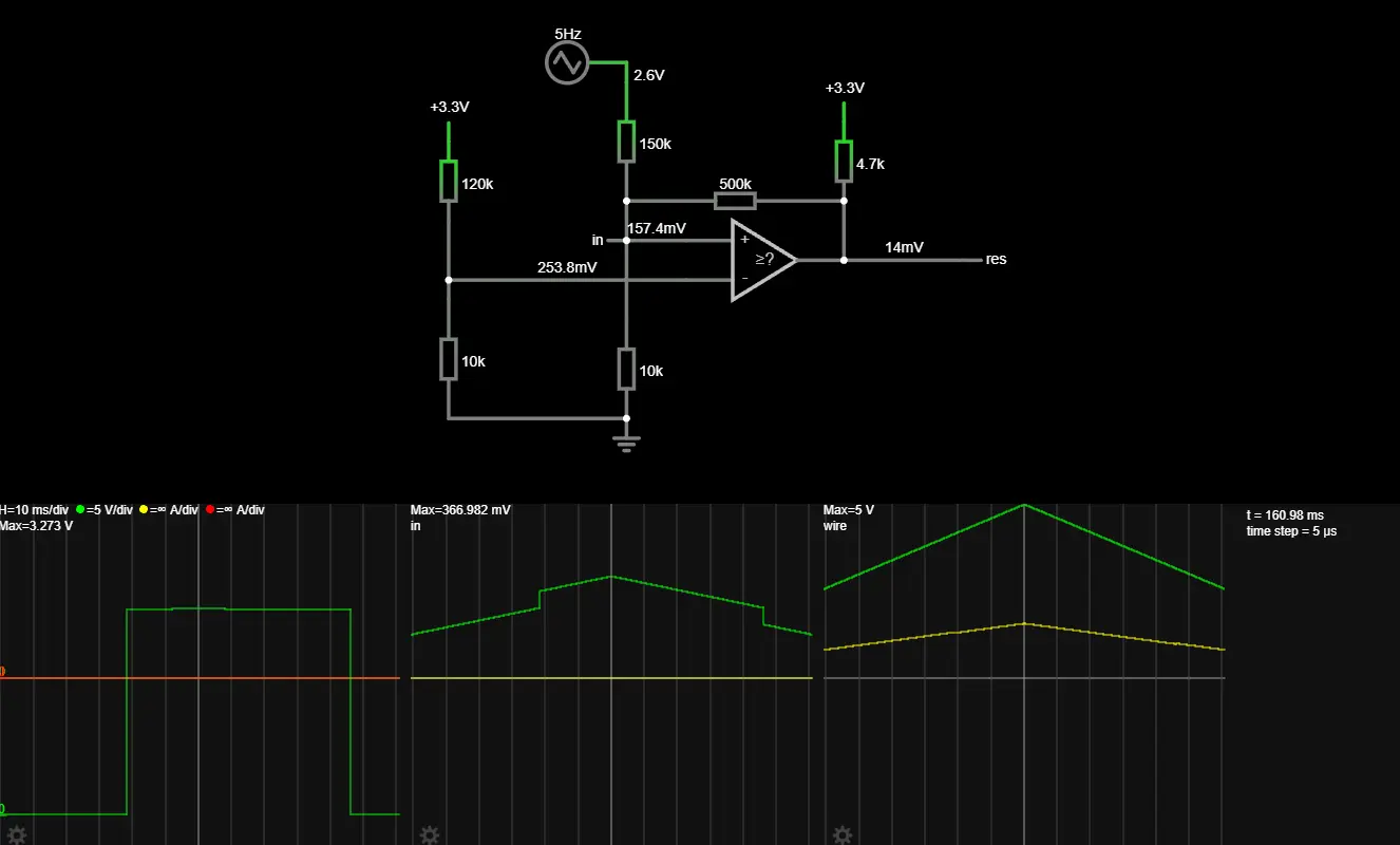
Here is a falstad simulation that shows the behaviour of the circuit around 4V.