DCC Command Station, Mk2
Second revision of my old DCC Command Station from 2021.
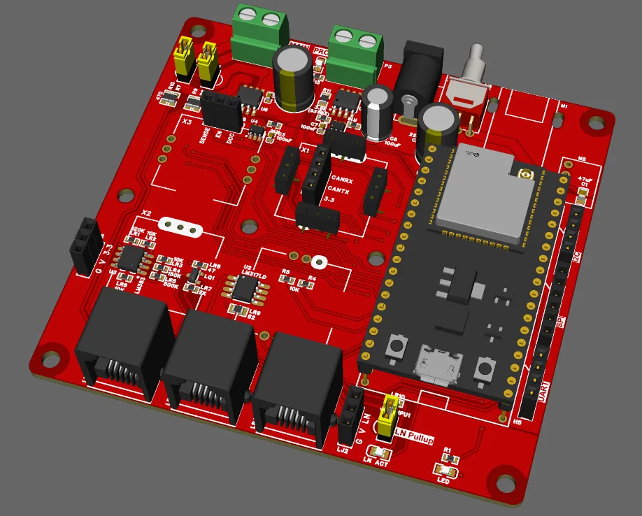
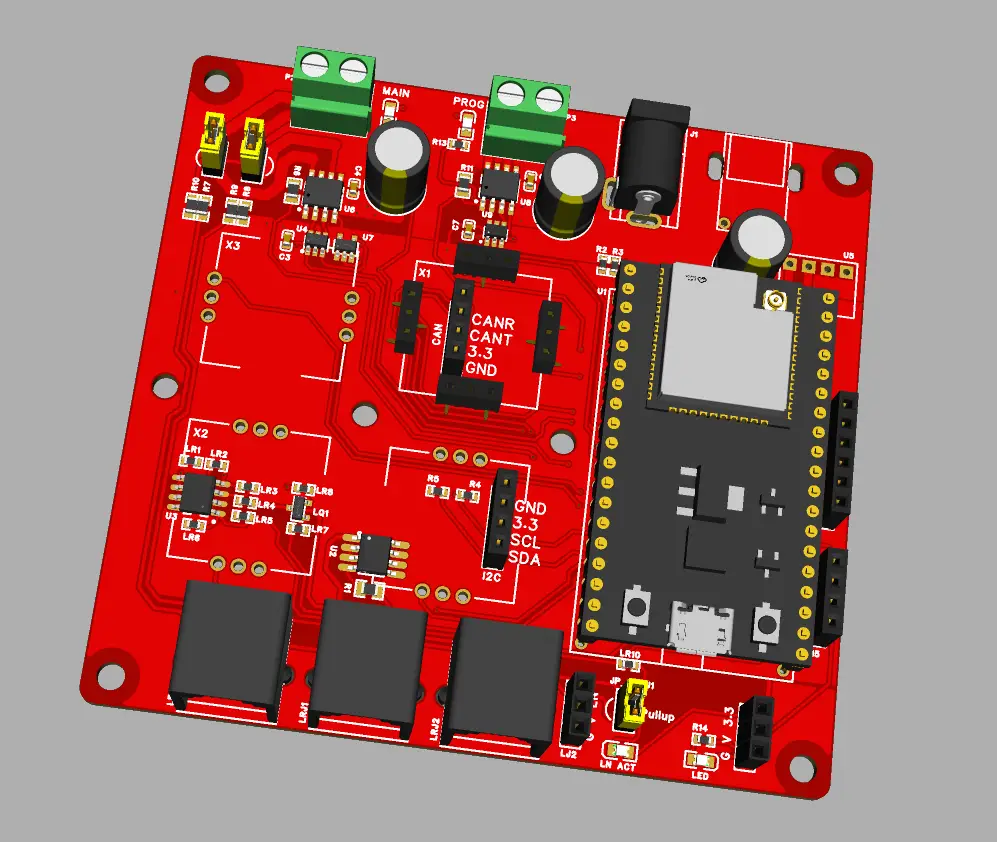
TL;DR: Sources
Firmware: LocoNetControlStation project. It’s still the same repository as for the Mk1, and codebase compiles for Mk1 and Mk2 depending on PlatformIO environment.
PCB Schematic: PDF of the v1.1 with fixes and improvements of the manufactured version that (that was 1.0).
Whole PCB Project: EasyEDA Pro (not approved yet as of now)
| The schematics and PCB layout are released, but I would consider it as an educational project for other people, rather than useful for recreating 1-to-1. I adapted it for my capabilities and needs, e.g. used components that I had in stock, will use full-color PCB because it’s cheaper with JLCPCB coupons, so it might not be the optimal to replicate 1-to-1. Same applies to firmware. |
Showcase
Requirements
For Mk2 hardware, I formulated these requirements:
-
Mounting in a DIN-rail enclosure
-
USB-PD power option
-
Screen for command station status display
-
Component base upgrade based on lessons learned since the first version
-
Modularity and potential for adding new functionality in the future—specifically RailCom and the LCC bus
-
Using ready-made off-the-shelf modules where possible instead of routing everything directly on the board
Requirements that remained unchanged since Mk1:
-
The brain of the station is still the ESP32
-
LocoNet remains the primary communication bus on the layout
Requirements for software:
-
Refresh the stack: SDK, libraries etc.
-
Add display and UI for diagnostic information, and maybe rudimentary control of the layout (e.g. turning power on/off)
-
Improve implementation of DCC, wiThrottle and LocoNet protocols In particular, send loco functions to tracks periodically (old version didn’t, which caused trains to forget the function states when loosing power).
Following sections dive into each of these requirements.
Form factor
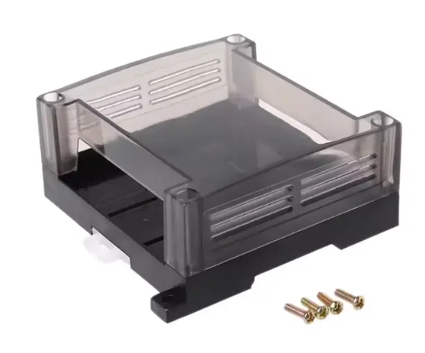
The first version of the command station was just a bare PCB with connectors sticking out in all directions, without any plan for enclosure mounting. A cased command station will look much more like a finished product, plus, putting a device in an enclosure is more convenient, practical, and safe. DIN-rail mounting seems like it will simplify installation on the layout. To be honest, I don’t know why this industrial standard isn’t more widely adopted in model train electronics world, at least for gear that isn’t bound to specific points on the layout and can be installed centrally, like command stations, boosters, power supplies, etc. To avoid the hassle of custom case design, I chose an off-the-shelf enclosure from AliExpress and designed the PCB around its dimensions.
Power supply
USB-PD is awesome and versatile! A small layout can be powered from a phone/tablet/laptop charger or a power bank. There are also USB-PD adapters that clip onto power tool batteries, which I regularly use in other projects. Such a power source would be able to supply larger layout for longer time. Just in case, the standard 5.5x2.1mm barrel jack is still there (though I considered removing it to save board space).
Display
The first version used a single MCU-controlled status LED (plus others for DCC output and LocoNet activity), which proved insufficient for diagnostic signals like "WiFi disconnected" or "Overcurrent". For the new version, I decided to add an OLED display that can show much more data, including active locomotives, connected throttles/hand controllers, input voltage, and more. Since I’m a fan of Amperka’s Troyka module ecosystem and already had a screen module made for it, I simply added a Troyka-compatible I2C header on the board.
Components refresh
H-Bridge: The first version used an L298N H-bridge simply because every Arduino enthusiast uses it, and it’s on the standard Arduino motor shield. It is actually quite an ancient (last-century) and highly inefficient chip. In the new version, I replaced it with TI’s modern DRV8251. Having tested the DRVxxxx family on several previous projects, I’ve been very pleased with those. The new chip comes in a much smaller footprint (SOIC-8 vs. MultiWatt15) and handles higher current (4.1A vs. 2A per channel) without a massive heatsink.
Another major advantage is its integrated current mirror for rail current sensing. With the L298N, all current had to pass through a multi-watt sense resistor. Over years of use, the original resistor even got discolored from heat (which is surprising, as I never pushed the station hard). The DRV8251’s current mirror outputs 1.5 mA per amp of load, so even at full load, only a few milliamps pass through the sense resistor.
Because the new H-bridge is single-channel (whereas the L298N was dual-channel), having both main and programming track requires a second chip. Additionally, because the old L298 was so inefficient and resource-heavy to produce, the DRV8251 actually costs several times less.
Microcontroller module: The old version used a Lolin32 Lite board, chosen because it was the cheapest ESP32 option. As it turned out, the Lolin32 Lite lacks a 5V input rail, forcing me to add a second 3.3V regulator on the main PCB. In the new version, I opted for a more standardized approach and picked the official ESP32-DevKitC from Espressif, chip manufacturer. Knockoffs are available on AliExpress for less; and while they usually have minor component issues, they work more or less fine. I chose the external antenna option over the PCB antenna to get better wireless range with throttles. The antenna can be mounted onto the case.
Power Regulator: I replaced the 7805 linear regulator with a switching buck converter. Because the ESP32 is a fairly power-hungry chip with Wi-Fi running, and input voltage is relatively high, the LM7805 was the hottest component on the old board; hot enough to burn your finger or to produce the smell of hot metal in the vicinity. The new version uses a tiny switching regulator module from AliExpress. Three of its four pins share the exact pinout of the 7805, making them drop-in interchangeable if needed.
Expandability The first version wasn’t designed for expandability, which caused headaches during debugging and code development for the new version. To avoid having to spin another board as soon as this one outgrows the requirements, I tried to anticipate future needs and designed the layout accordingly:
RailCom: This is the primary candidate for future addition and the trickiest to implement, as DCC output circuitry with RailCom differs significantly from standard DCC output. To prepare for this, I placed a jumper in front of the DCC output connector that routes signals to the onboard H-bridge by default. To do things right, the DCC signal sent to the LocoNet bus must not contain RailCom cutout gaps, requiring a dedicated, independent H-bridge for LocoNet (which also helps fulfill LocoNet’s distinct current requirements). To keep the current layout simple while staying future-proof, adding RailCom later will just mean adding a second H-bridge, tying it to the DCC output and MCU pins, and assigning the existing onboard bridge entirely to LocoNet. For this RailCom board, a troyka module footprint is palced near DCC main circuitry.
LCC Bus: For potential LCC support, I routed CAN RX/TX lines to an expansion header.
General I/O: For everything else that might come up, UART, SPI, and I2C communication lines are broken out to separate headers. Additionally, space is allocated for 4 Troyka modules: two occupied by the display, leaving two free for expansion. Any unassigned module pins can simply be jumpered to free MCU pins.
Software changes
-
Actualize toolchains, update ESP32 SDK, libraries. The project was last actively worked on in 2021, so everything is rather encient. I was surprised that it still compiles, though.
-
Regularly send (refresh) function states to locomotives (old code only sends loco speed/direction packets, this was an issue I noticed while running on dirty tracks).
-
Display diagnostic info on OLED display (it shows number of WiThrottle/LbServer clients, track power state, number of running trains and some other)
-
Fast clock support on LocoNet, WiThrottle (and, in future, DCC)
-
Better processing of LocoNet turnout commands (also fixed some bugs with LocoNet slot ownership and dispatching)
-
WiThrottle has support for "steal" messages, and fast clock too.
DCC pulse generation in ESP-IDF 5
Upgrading code to ESP-IDF v5 proved to be a major challenge. New timer API caused the DCC bit timings to break, as the jitter in timer callbacks was too large in the new API for some reason. So I switched to RMT peripheral, but it’s also suffering from problems due to delays between RMT transmissions, which make it non-ideal for continous streaming. Even worse, in the new SDK RMT peripheral has completely new API which doesn’t allow continous streaming. So, a legacy RMT driver was used for uninterrupted streaming. Because it’s designated legacy and completely removed in ESP-IDF 6, I decided to copy it from ESP-IDF 5 and store it as a library in repository (project still uses SDK 5 though). The idea comes from the issue discussion above: RMT is configured to loop infinitely; DCC packet preamble is sent out first, and while it’s sent, there is enough time to put the rest of the packet into RMT memory. This way pulse generation is continous and doesn’t suffer from IST latency and task switching. The implementation has limitations on DCC packet size, it’s limited to RMT block memory allocated to channel. ESP32 has 64 symbols (=DCC bits) per block, of which it it has 8, so it’s not a problem for original ESP32, but can be a major limitation for newer ESP32s (they have much smaller buffers).
New DCC packet refreshing system
Another major task was refreshing of function packets on DCC track. This required inventing some kind of a priority queue backed by table of alocated locomotives so that each locomotive regularly receives both a speed/dir DCC packet and a function packet (3 groups of functions are cycled through, totalling 12 functions). Other, non-locomotive packets go through the queue directly and get picked up by DCC pulse generator according to their priority. For now priority system is rather simple, stop and emergency stop packets have higher priority than normal packets.
A lot of other work was done, I’ve spent a month in total on the software, I think. There are still some major improvements possible, like handling of various messages via a application-wide message bus and processing physical LocoNet packets in a separate task (to not block other tasks that initiate communication).
After-assembly fixes
After ordering the production of the PCB I’ve made some improvements. And during its assembly and testing I notices some problems that needed fixing, one quite critical. Luckily, the critical fixes were possible without re-ordering the PCB. The changes are now part of v1.1 of the design.
-
Disconnected 3rd pin of barrel jack from GND (it may be used in future to test presence of the connector)
-
Made DCC output wires wider for more current
-
Routed GND+3V3 to display 2nd header (so it can be used for other purposes when no display is present)
-
Added silkscreen pinnames to ESP32 (was useful once or twice on Mk1)
-
Changed prog current to ~500mA (to prevent chip built-in protection from tripping)
-
Improved LocoNet RX circuit (see this post)
-
!!! Fixed LocoNet pullup IC (was incorrectly wired. Interestingly, in 2021 version too.)
-
!!! Fixed U4 pins (it lead to main DCC output not working)
-
Added power switch, moved connectors around for move even spacing.