Motor control board
A small PCB to control motors in small-scale models. I’ve developed it as part of the portal crane.


| A newer iteration of this project has a separate page. |
Description
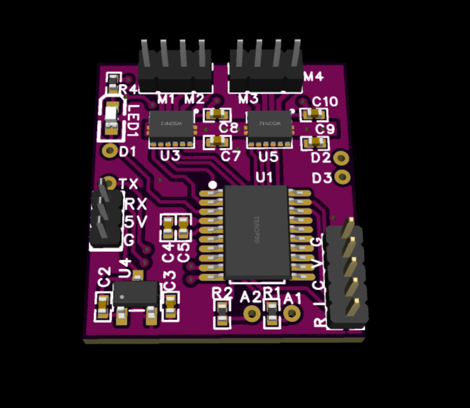
On highest level, the board contains an MCU and 2 dual H-bridges, so it can control 4 DC motors. I challenged myself to make it as small as possible (without going to the extremes), so its size is 18mm x 20mm. For reference, Arduino Nano board is 18mm x 45mm, so this project is more than 2 times smaller. For the sake of miniaturization, all headers are 1.27mm pitched (not breadboard friendly).
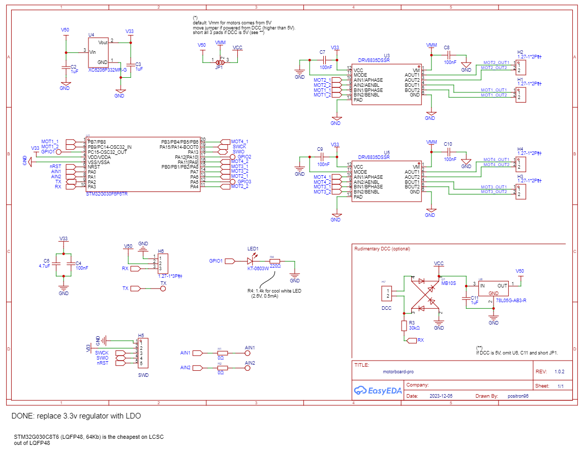
The MCU is an STM32G030 in TSSOP20 package. It has 32KB flash, 8KB RAM, more than enough for the task. I wanted to try the newer STM32G-series controllers, and see how much better they are, compared to F-series. Indeed, the power pins are more easy to use (there is only one pair of VCC+GND, so only one set of bypass capacitors is needed), more GPIO pins are available, which is useful on smaller packages (less bootstrap pins are required, less power pins, crystal-less operation also works fine). All its pins that are not used for motors are routed to solderable pads, so they can be used for extra functionality. There are 5 spare GPIOs left (6 if you don’t need UART TX), they can be used to connect servos, LEDs or endstops. One of them controls a LED on board. 2 pins are routed to pads via resistors (0 Ohm in schematic, to be defined for particular use-case), other 3 pins are directly available.
The H-bridges are TI DRV8835, 12V, 1.5A dual motor drivers. To keep the board small, WSON package devices are used.
The current crane idea (and capabilities of slip ring) is to pass 3 wires to the board from the ground: GND, 5V and UART RX.
However, for a possible future use-case, a simple DCC-like interface is provided. For this, the board has 2 separate pads, which are routed to a rectifier, 5V regulator, which then feeds 3.3V LDO. One of the pads is also fed into MCU GPIO with a large resistor. The technique is not ideal, but should be OK for DIY-grade projects, I’ve seen a DCC interface implemented like this in working projects. A proper way to read DCC signal is with optocoupler. Replying to DCC commands relies on sinking power into motor, so it depends on what motor will be connected. Crane motors will not take required power (probably), but I don’t plan to use crane in DCC mode anyway.
Manufacturing

The board was ordered at JLCPCB, along with components from LCSC. Currently it’s not available to ship them as one order, but LCSC gives a discount if there is a PCB order in parallel. In my case it was 100% discount on shipping cost. More logistics details can be read here and older one, here.
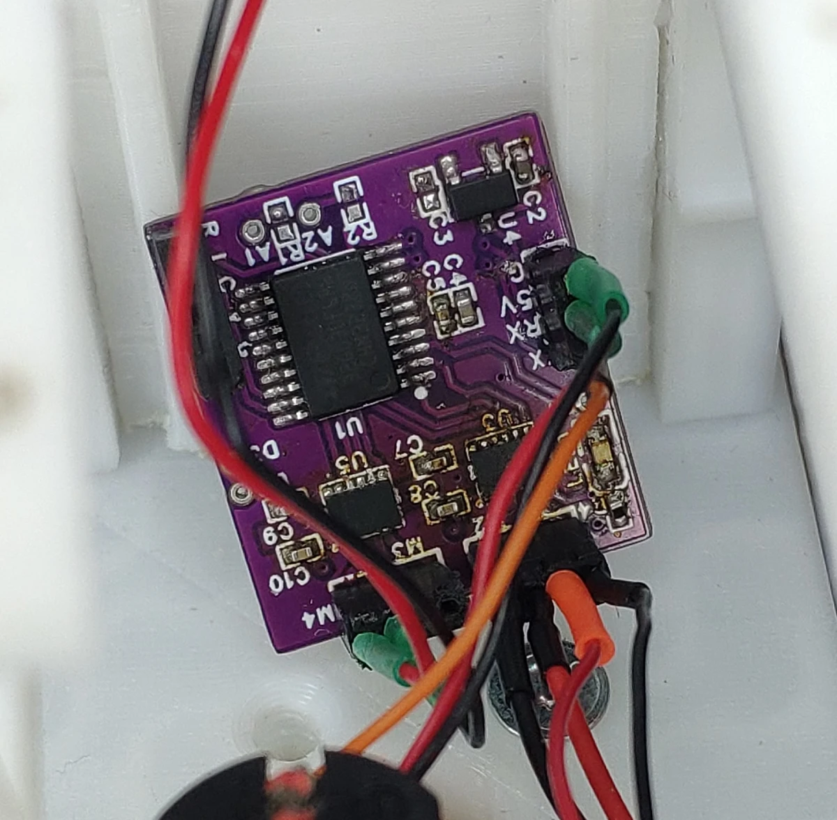
All of the components except H-bridges was soldered by hand with a T12 soldering iron. H-bridges were more tricky to solder as they come in a lead-less packages. I used a heat gun (from a rework soldering station), and after a dozen attempts both ICs were soldered. The PCB got a bit discolored, near the H-brides area. I hope next time I’ll have more skill.
All in all, 0402 components were doable, but I’d rather use 0603 next time if space is of less concern.
Firmware
Firmware is written using CubeMX tool in VSCode IDE with PlatformIO extension. It uses a wonderful C++ ETLCPP library. At the moment it’s not open-source.
Communication protocol
The firmware accepts UART data on UART2_RX (PA3) pin, 115200 baud, 8N1.
At the moment, it accepts 2 commands for motors and outputs.
Each command ends with a newline (\n).
Size of RX buffer is 32 bytes, command must fit into it fully.
Commands consist of tokens separated by spaces (or commas or combination thereof).
Motor command sets motors speeds, all at one.
Format is M 1 2 3 4,
where 1,2,3 and 4 are motor speeds for respective motors.
The values are in -127..127 range
(yes, I didn’t want to bother with one more negative value).
Output command controls GPIO outputs. Format is O 1 0,
where "1" is output number
(valid are 0, 1, 2, output 0 has a LED and is used for system state indication,
so usage is discouraged),
"0" is output state (valid are 0 and 1).
If no valid commands are received within 1s, the motors are stopped. This is a measure to prevent runaway in case of communication loss (which is a possibility with a handmade slip ring).
UART2_TX (PA2) pin sends log messages.
Wireless RC expansion
There is also an idea to connect the motor board to a BLE UART bridge, attach some Li-Ion battery and get an almost-ready solution for RC vehicles.
This project has now separate section.