BLE-based micro scale RC receiver
Project description
The idea is to make an RC receiver for 1:87 scale vehicles, but with BLE instead of usual 2.4GHz technologies. The benefits of BLE are that it’s bidirectional by design, supported directly by modern smartphones, transmitter can be made from typical hobby electronic components (for example, ESP32). The downside is worse range (BLE seems to use less Tx power), but for 1:87 scale the range at which the vehicles are used is very small anyway (compared to traditional RC vehicles like airplanes and outdoor cars). It remains to be seen whether the range is sufficient.
Design goals:
-
Power: 1 Li-Ion cell
-
BLE. UART-over-BLE or something similarly simple.
-
At least 1 DC motor (cars need 1 motor, excavator needs 6, while tractors, loaders and forklifts are somewhere in between)
-
Some servo outputs (servo outputs can also solve lack of H-bridges if more motors are needed)
-
Some generic GPIO outputs (can also be used to connect external H-bridges if needed). In theory, servo and GPIO outputs only differ in firmware (and pin PWM capability).
-
On-board antenna.
-
Size: around 14x10mm (equals size of some Das87 receivers).
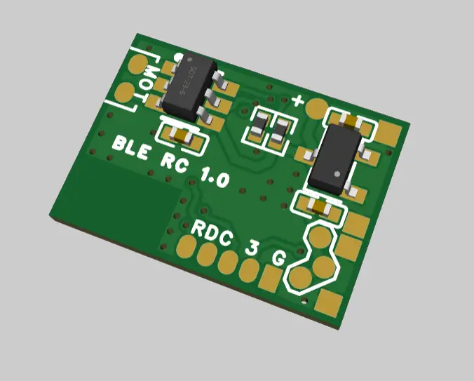
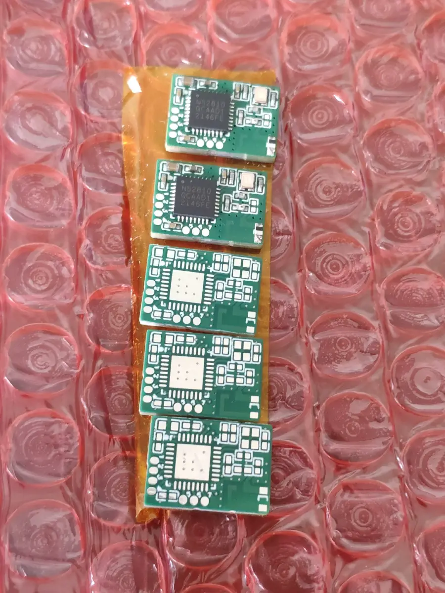
After doing some research on component selection, I decided to design my PCB with a chip antenna and nRF52810 MCU. This allows the whole setup be very compact (10x14mm), and gives pleasure of learning to design a new PCB. There is a possibility that it will have poor radio performance due to unmatched impedances and other suboptimal design elements.
Demo
Here is a video of a model that uses it:
More details about the model are here: /projects/rc-kit-1.
Hardware
The PCB and schematic can be viewed in easyEDA Pro here: https://pro.easyeda.com/editor#id=5f86e326cba74d64a7422a910f110782

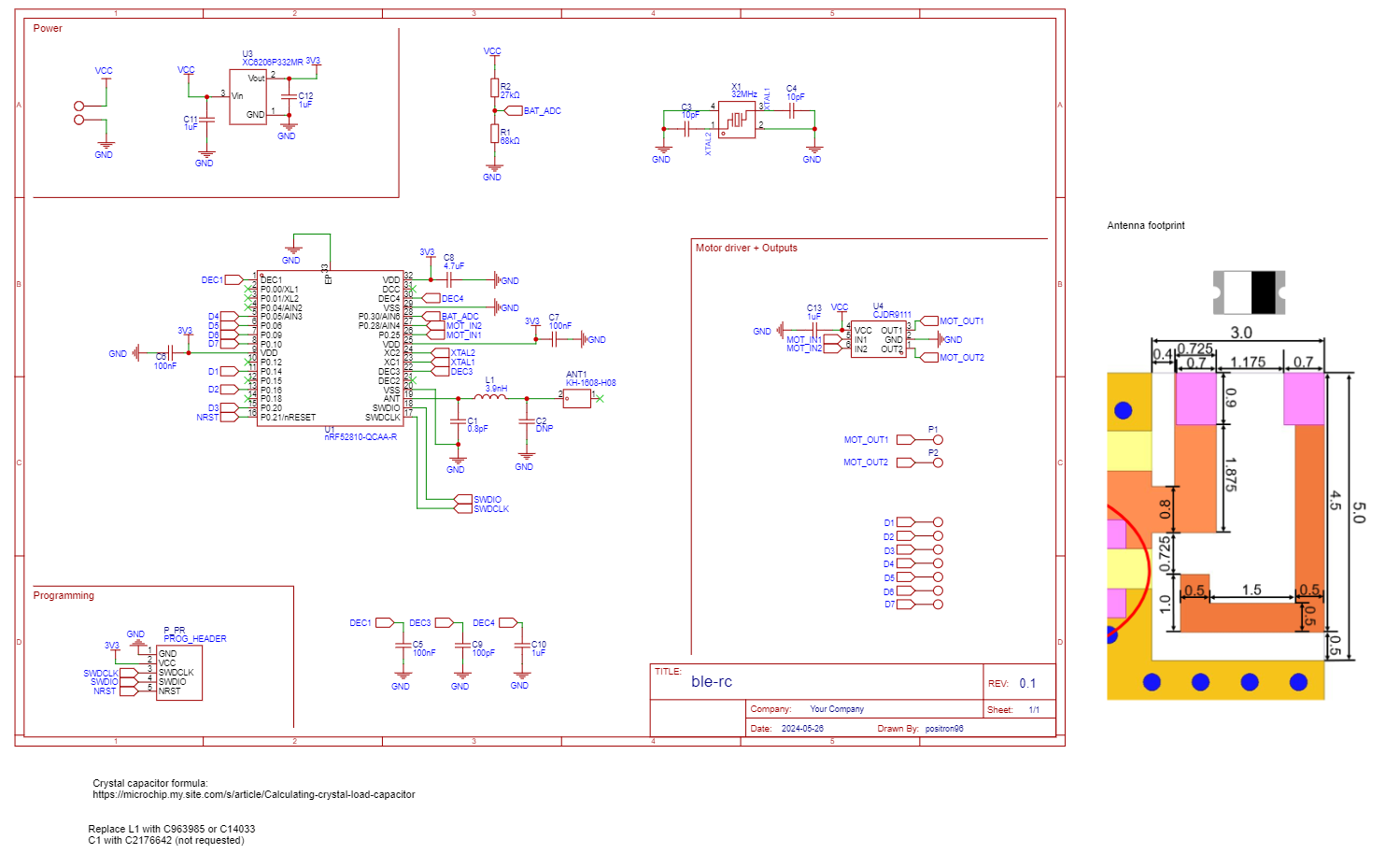
In future revisions an nRF52811 can be also tested, as it has BLE Long Range feature, but at the moment QFN32 package is not available on JLCPCB.
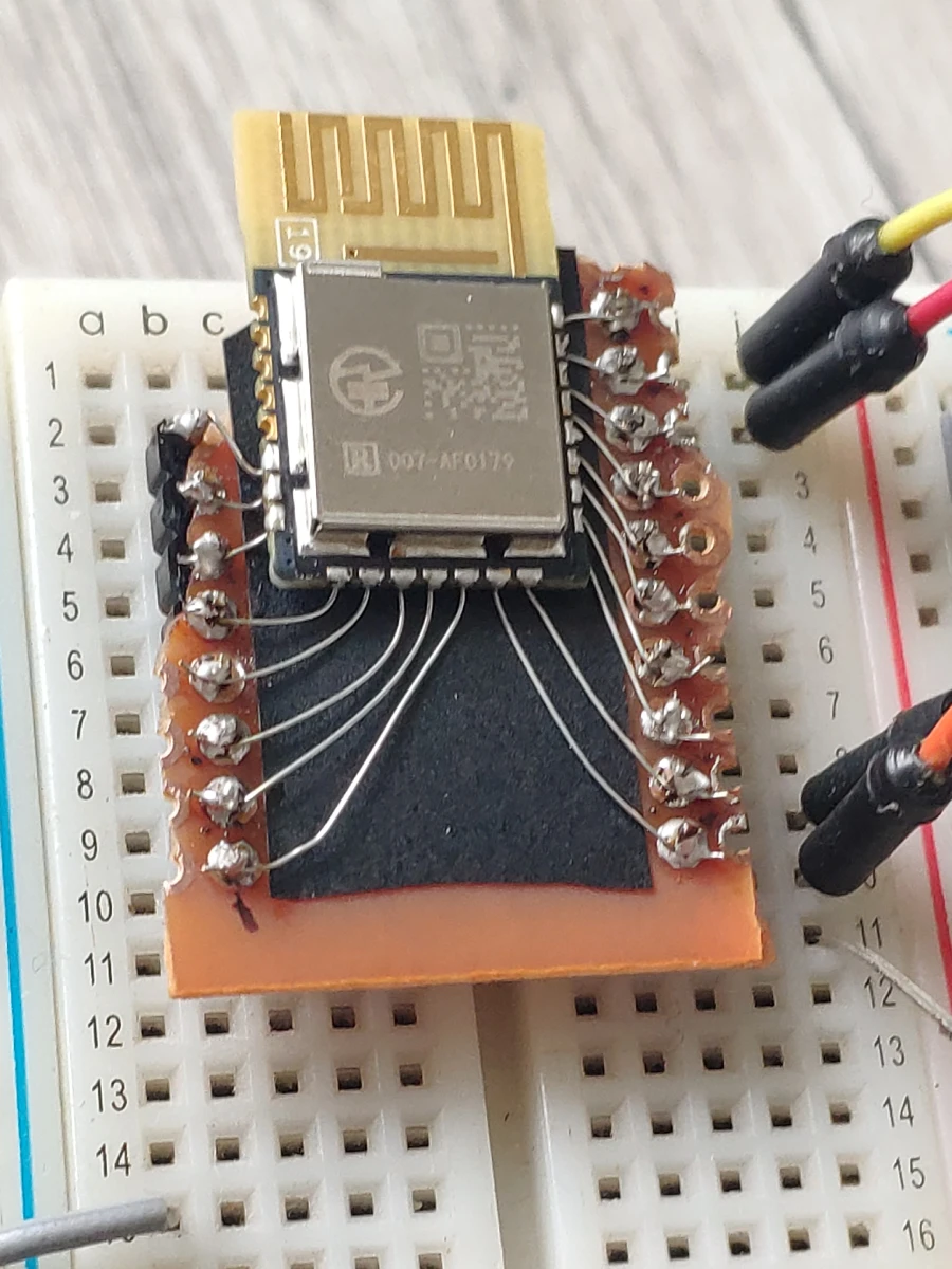
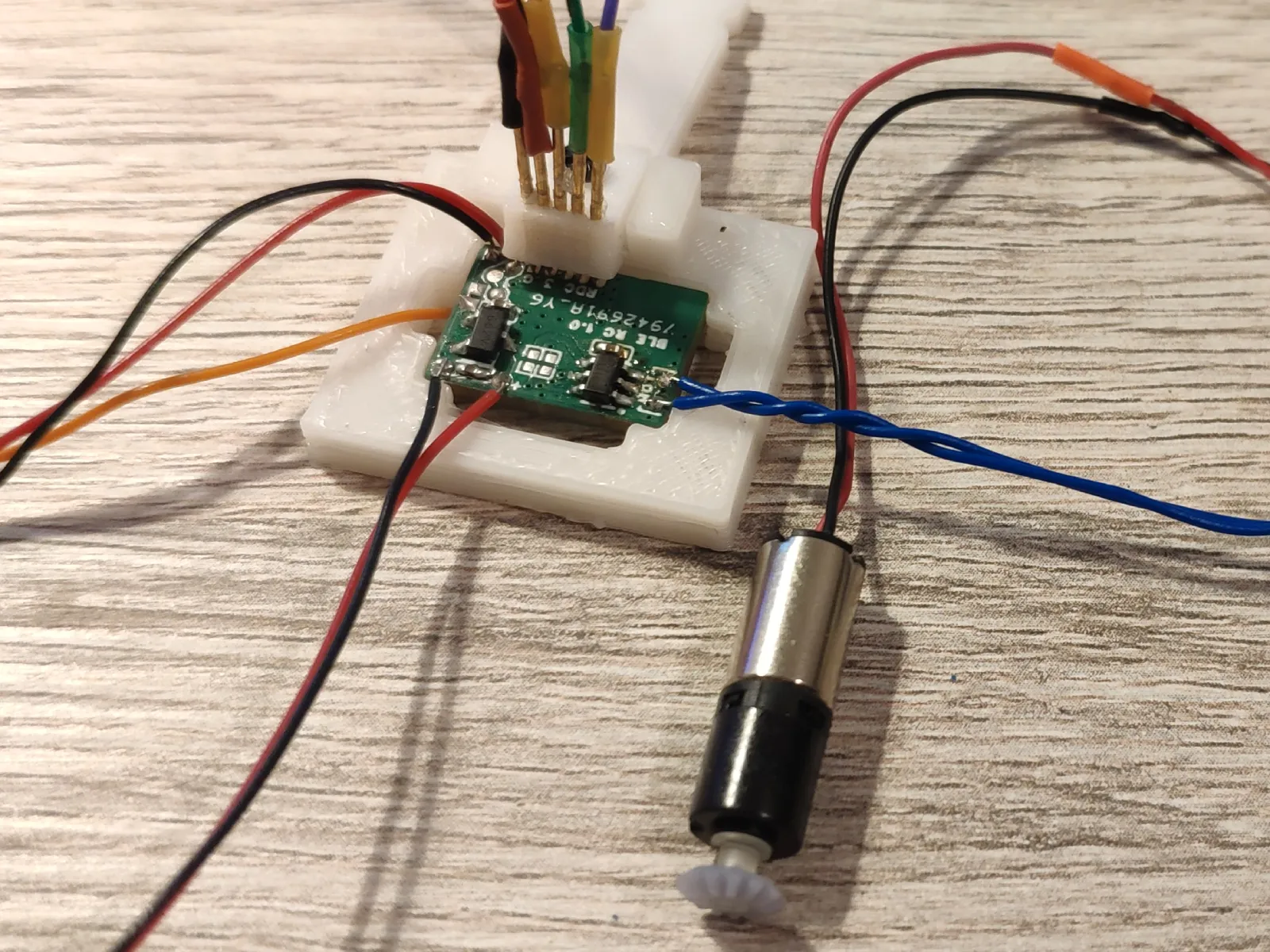
For initial development and subsequent validation testing I’ve got a ready-made module with nRF52810, called AF0179. AliExpress seller sent me this document with pinout (in chineese). The documentation states that the module can have an AT-commands firmware, but mine is empty. The module has 1.27mm castellated holes, so it requires some work to make it breadboard-compatible.
The 1st version of PCBs designed for the project seems to work quite fine. The range is less than from PCB antenna on AF0179 module, but seems to ge good enough for the use-case (line-of-sight distance of couple meters).
Firmware research
There are quite a lot of options of frameworks for the MCU.
Nordic Semiconductor offers 2 ways to program the board:
-
New Nrf Connect SDK (ZephyrOS-based)
-
Old SoftDevice-based (a BLE stack is added as a binary blob).
There is also a library "nrfx" from Nordic that is a HAL for everything except BLE (more precisely, it’s 3 layers, the lowest is thin wrapper over SVD-derived register manipulation, the highest wraps all this in structures and high-level functions). BLE stack comes as a separate codebase, there are 3 options: SoftDevice (binary blob), Zephyr (open source) and NimBLE (also open source). Both Zephyr and NimBLE use nrfx library, but that’s well hidden inside the stacks.
The NimBLE stack is a part of Apache Mynewt RTOS. So it works with Mynewt OS best, but can be used with other RTOSes, including FreeRTOS (and it seems that some ESP32 BLE libraries use NimBLE on top of FreeRTOS).
For PlatformIO-based development there are a few options as well.
-
Zephyr framework is supported up to v2.7 (current version from nRF Connect is 3.6, a ticket to support v3 is open since 2021 on PlatformIO github).
-
There is an Arduino framework that uses SoftDevice SDK. Arduino framework for Adafruit-produced boards uses custom Arafruit code based on SoftDevices and FreeRTOS.
-
There is also an mbed-based framework.
-
Then there is a user-made Arduino n-able core which uses FreeRTOS, nrfx and Arduino-looking BLE library based on NimBLE.
I’ve found a good tutorial on adding custom nRF52 boards to PlatformIO Zephyr project: https://piolabs.com/blog/engineering/platformio-zephyr-custom-hardware.html. With its help I was able to start minimal examples of Zephyr OS (blinky and a BLE beacon). As I understand, its idea is to configure all the hardware statically in a form of device-tree (a technology from Linux world), generate initialization code based on it and run it at boot time. If you want to remap PWM peripheral to a different pin (what can be achieved in a couple register writes on bare-metal), then you need to go to underlying nrfx. A minimal BLE example uses 16KB of RAM, about 60% total, which is bad.
Both arduino frameworks don’t support nRF52810 out of the box and require changes to the platform python code and framework code. My attempt at adding the support to n-able core is shown here: https://github.com/h2zero/n-able-Arduino/pull/46. It works, but BLE example consumes ~70% of RAM, which needs further tweaking.
I also tried a mynewt+nimble example without any PlatformIO, seems like flash and RAM consumption are even worse. Also didn’t like that separate tool is required to configure the project and download components, and it downloads several GBs of components.
Firmware development
So I’ve decided to use SoftDevice-based workflow. To use it with PlatformIO tools, I’ve made separate "platform" and "framework" that package a Nordic SoftDevice SDK.
The firmware project itself is hosted here: https://github.com/positron96/rc-ble and has MIT-license.
The PlatformIO components are here: PlatformIO platform, PlatformIO framework (they will be downloaded automatically when you open the FW project in PlatformIO).
Good thing about Nordic MCUs is that they can map any peripheral to any of the pins, so using PWM on any of the pins is not a problem.
nRF52810 has one PWM peripheral with 4 channels, so the easy way to use it is to wire 2 H-bridge pins and 2 LEDs to it. By swapping one PWM channel over one of 2 motor pins (with an H-bridge, one pin does PWM and the other one is fixed at 0V) can free 3 pins for LEDs. Juggling pins can introduce delays and noise into other pins and cause LEDs flickering, so it needs to be investigated.
Communication
Communication is via UART-like interface over BLE. For now I am just using UUIDs of Nordic UART Service (NUS).
Basic commands follow typical RC protocols that simply contain values for each control channel. These commands are separated by newline (“\n”).
Command |
Description |
|
Set channel N to value V (uint8, center is 128). and come in form So far there are 3 channels, 0=throttle, 1=steering, 2=headlights, 3=marker lights. |
|
Reboot into DFU mode (see below). |
|
Change center value of steer servo to Nus |
|
Whether to invert drive direction. |
PDM instead of PWM
The MCU has 4 PWM channels, of which 2 channels are reserved for motor, which leaves only 2 PWM outputs for LEDs. There is also 1 unoccupied timer (or 2, depends on what SDK is used) that can control 3 more pins (also depends on number of free PPI lines), but it is used for servos, so its frequency is too low for LEDs.
More dimming-capable LEDs can be provided by software-based Pulse Density Modulation (PDM) outputs (this can leave hardware PWM for motor and a timer for servos).
I learned about it from the article that applies Bresenham line-drawing algorithm to bit-banging PWM, but since then I realized that in electronics this algorithm is more conventionally called PDM, or even 1-bit sigma-delta DAC.
The approach needs to periodically update pin value (from a timer interrupt), but, compared to PWM, it’s output has perceivably higher frequency rate. A 8-bit PWM generated by 1KHz timer has 256ms period, so ~4 Hz total frequency, but PDM will toggle GPIO state with 1KHz rate, so it will have much less flicker. In high or low fill rates it still does not toggle the pin as much, to flicker will still be noticeable.
This software PDM method can bring analog output to any number of pins, but has limitations. In works in principle, and looks good even at low timer frequencies (1 kHz), but at low duty cycles it produces significant flickering. I would advice using it for smooth turn-on or off animations, where low duty cycle values last only for a fraction of a second and lowest values are skipped entirely.
OTA updates
Having OTA updates is very beneficial in this application (because it is be very difficult to reflash the PCB when it’s installed in the model), Nimble and n-able core do not support OTA, so they cannot be used.
Zephyr supports OTA by having a MCUboot bootloader that lets the firmware itself recieve a new version, store it in a free half of flash, and overwrite the new firmware over the old one. So the the firmware must occupy less than half of the flash, which is problematic for an nRF52810 with 192 Kb of flash. Only BLE stack alone occupies ~100Kb.
nRF SDK also allows OTA, and it has a very different approach. Since the SoftDevice (BLE stack) is separated from the user firmware,
-
they can be flashed separately and firmware can be distributed without SoftDevice,
-
a relatively small bootloader can utilize BLE by using same SoftDevice blob as the firmware.
So when the MCU boots into bootloader, it starts BLE DFU service (or other methods of accepting the FW, but we are interested only in BLE), Nordic tools can connect to it and upload a firmware, the bootloader stores it into free part of flash (or overwrites existing firmware in place), verifies its checksum (or optionally a cryptographic signature) and moves it to proper position. The bootloader shows with a different MAC and under the name "DFUTarg". Only the user firmware without BLE stack needs to be flashed, so the transfer size is ~20Kb.
A remote to control the project
There is an ongoing project to develop a physical remote with BLE capability to interface with the receiver.
However, as it’s not ready yet, for now I am using a rudimentary Android application. It’s created in MIT App Inventor service, which allows to make mobile apps in browser, using block-based programming language.
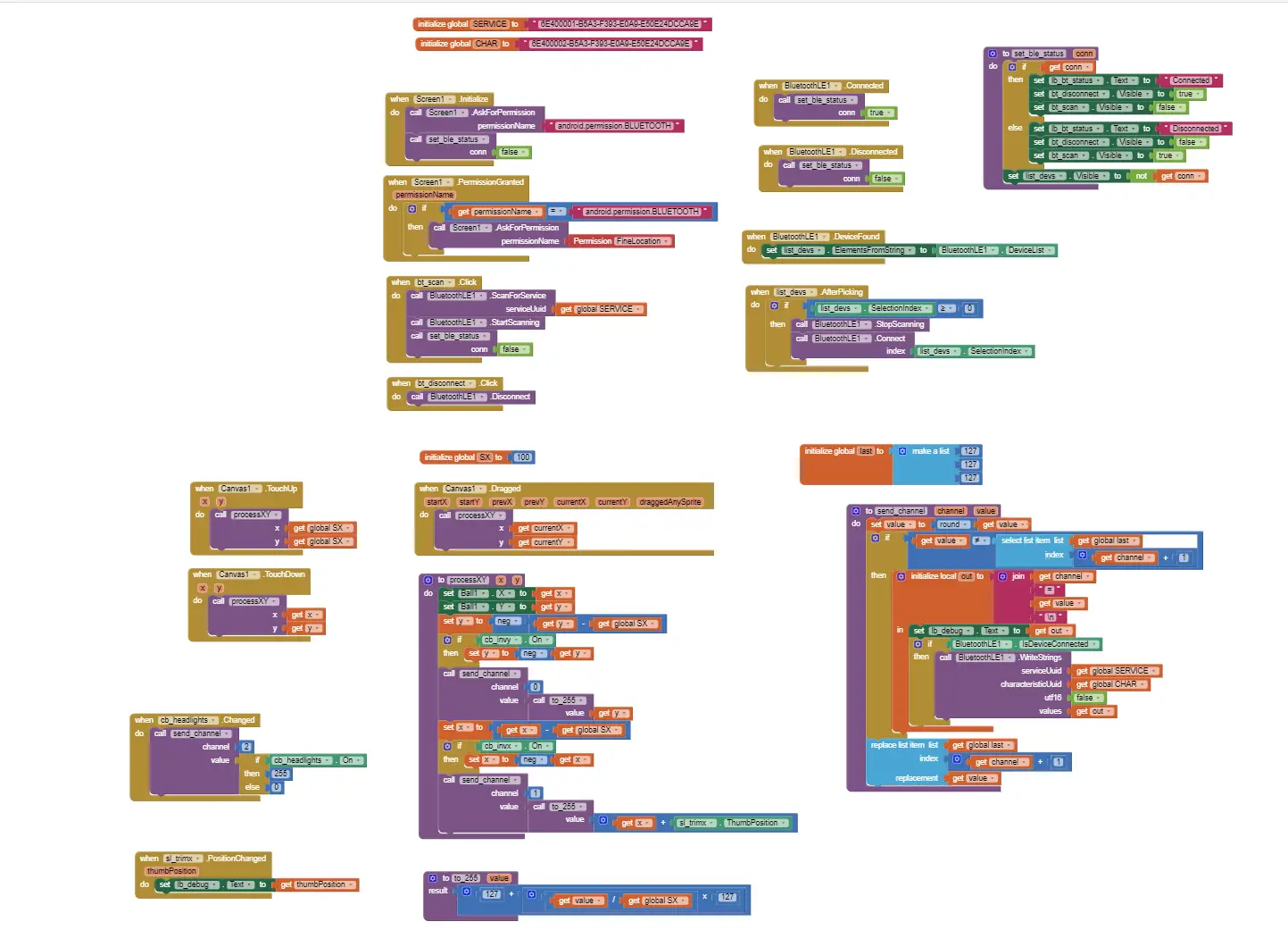
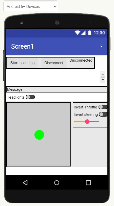
It doesn’t seem like MIT App Inventor projects can be shared online, I’ll make a downloadable archive sometime later.
Links
-
PCB project: https://oshwlab.com/positron96/ble-rc
-
Firmware project: https://github.com/positron96/rc-ble
-
Application of this project: /projects/rc-kit-1
-
nRF52810 Product specification: https://docs.nordicsemi.com/bundle/nRF52810_PS_v1.5/resource/nRF52810_PS_v1.5.pdf