World’s smallest (possibly) Li-Ion protection PCB
Rationale
A lot of Li-Ion batteries come with protection PCB inside. This is necessary because the chemistry inside is volatile, so it’s not unheard of batteries busting into flames in case of improper handling, e.g. overcharging or overloading. Also lithium batteries can supply quite a lot of current, which needs to be limited in cases when something goes wrong, which happens a lot during development or assembly of the DIY projects.
A typical protection PCB contains a monitoring chip like a very famous and cheap DW01A (it or its clones can be found in most cheap power banks or anything with lithium batteries) and a pair of MOSFETs in a single package. A pair is needed to block current in both ways, during charge and discharge, otherwise one MOSFET will block current in only one direction and pass in reverse via its body diode.
Monitor chip also measures voltage drop across the MOSFETs, thus estimating the current passing through.
|
Typically by choosing MOSFET’s Rdson, the designer can select overcurrent and short-circuit threshold. This is only viable, though, for currents of several amperes and most of readily-available protection PCBs have a limit of around 3-5A. To limit current at lower levels, say, couple hundreds milliamperes, choosing MOSFETs with high Rdson becomes impractical. Which means that for projects with small current draw, the built-in overcurrent protection is not very useful as it never triggers during normal operation. If proper charging hardware is used, overvoltage protection is also not very useful. On the other hand, undervoltage protection is the most useful feature when operating the project. |
Thing is, the smaller the battery, the lower the chance that it will come with protection PCB. For example, batteries from TWS (True Wireless) earbuds never come with protection. I’ve sourced multiple batteries from them, never seen a dedicated protection. Hopefully, there is one on main earbud PCB. TWS charger case, on the other hand, have a larger battery and those sometimes come with protection board. At least I’ve found it once, but when I ordered same model for second time, the battery was without protection, most probably to optimize costs, as usual.
So for the smallest DIY projects I’ve decided to design my own 1-cell Li-Ion protection PCB. There are 2 iterations of the projects, both designed in EasyEDA and manufactured by JLCPCB.
An example of tiny battery-powered project. The video was made when I had made Mk1 PCB which didn’t fit in there, so there was no protection in the project.
Both designs are open-source and can be found here: https://oshwlab.com/positron96/battery-protection
Mk1, 10x10mm mm, DW01+MOSFETs
My first attempt just copies typical protection schematic in a more compact format.
It is based on DW01 IC with FS8205 dual MOSFETs, both in SOT-23 package. The PCB has size 9.8x9.8mm, which roughly matches the size of TWS earbud battery. It should be put on top of the battery and secured with capton tape.
On OSHW project page this is a subproject "10x10mm".
Mk2, 4x8mm, single IC
After Mk1, I’ve learned about existence of integrated battery protection chips that combine monitoring circuitry and switching MOSFETs into one package.
As far as I remember, it was in one of bigclive youtube videos.
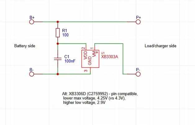
So the next iteration uses one of those, the XB3306 IC. It comes in SOT-23 package, has overcurrent threshold of 3A, undervoltage threshold of 2.4V.
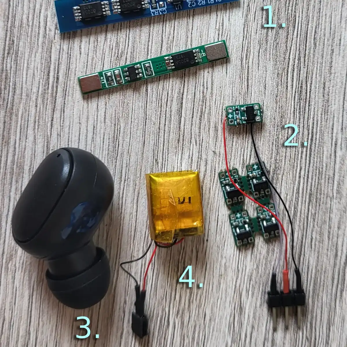
On the photo:
-
Two standard Li-Ion protection PCBs from Aliexpress — cheap, easily available, but very nig for tiny projects.
-
Mk2 PCBs — 1 separated, 4 still on the panel from PCB manufacturer.
-
A typical TWS (True Wireless Stereo) headphone.
-
A battery from the TWS headphone, no built-in protection.
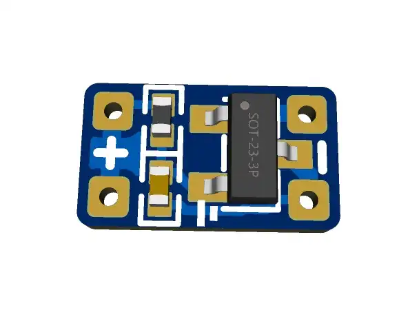
The PCB is 4x8mm and can fit into empty space of battery plastic bag where the contacts come out of the bag (which is where the protection PCB is placed on larger batteries).
On OSHW project page this is a subproject "tiny_4x8mm".
|
Don’t buy these ICs from aliexpress!
What I got from them are ICs with markings different from datasheet,
one out of 3 that I tested was dead on arrival,
and I couldn’t make over-voltage protection work,
(though that could be due to my testing procedures).
|
| XB3306 has an undervoltage level of 2.4V, which could be rather low for low-power scenarios. Overvoltage level is also somewhat high at 4.3V. I’ve found a pin-compatible IC XB3306D with unvervoltage threshold of 2.9V and overvoltage threshold of 4.25V. These values seem more friendly to batteries, so next batch will have thess ICs. |
| Thanks to bigclivedotcom video, I’ve recently found a similar integrated chip DW02, presumably from the same designers as DW01. It has 3A overcurrent protection, 4.3V/2.4V over- and undervoltage protection, which also seems that it could be lower. The IC is in SOT23-5 package, so is not pin-compatible with the XB3306 range. |